Vu Orthodontics - Orthodontics, Periodontics, and Implants
16027 Brookhurst St., Ste. K
Fountain Valley, CA 92708
ph: 714-775-0100
fax: 714-463-2205
drhungvu
Implants
Introduction
A natural tooth should be saved first, and a dental implant should be the last option.
Poor Implant Placement
A case of bad implant placement (which was done elsewhere) is shown in Fig. 1. In this case, the implant was placed not parallel to the adjacent roots. Its axis should be along the yellow line -- not the red one. It was also placed too deep. More importantly, the implant is of the wrong type. It is a tissue-level implant (of Straumann), so the top part of the implant should be above the bone level -- should not be below the bone level, as shown.
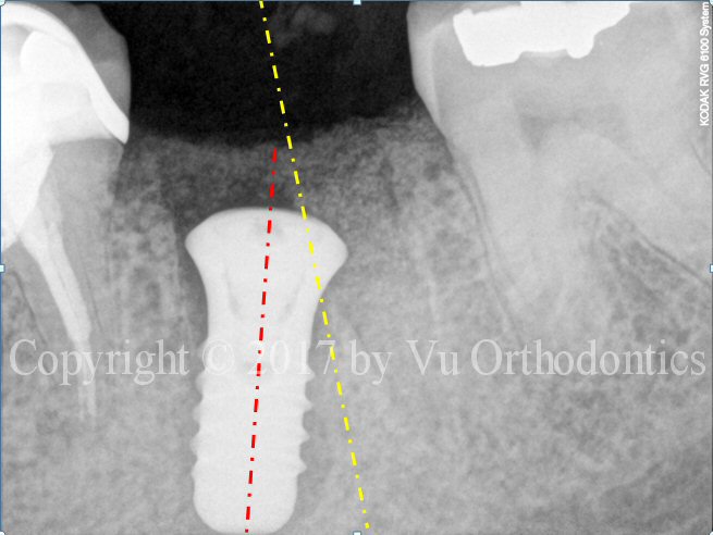
Fig. 1. Bad implant placement: the axis is supposed to follow the yellow line, not the red one.
Another case of poor implant placement (which was done elsewhere) is shown in Fig. 2. In this case, the implant (in the middle) caused a damage to the adjacent natural tooth.
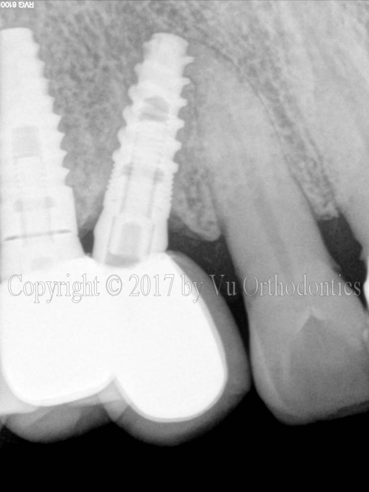
Fig. 2. Another poor implant placement
Another case of bad implant placement (which was done elsewhere) is shown in Fig. 3 (photo) and Fig. 4 (cross-sections of the CBCT scan). In this case, the implant is almost completely out of the bone. The site is of the upper right second premolar (Tooth #4). Even if the dentist had placed the implant in a perfect position and orientation, the bone width (in buccal-palatal direction) would still have been too small for this implant (6.22 mm, measured at the implant-platform level). According to the patient, the dentist who placed three (3) implants on him. But two (2) fell out, and only one remains. The dentist took some radiograph(s), presumably, PA or BW or both, and then told the patient, "The bone looks good."
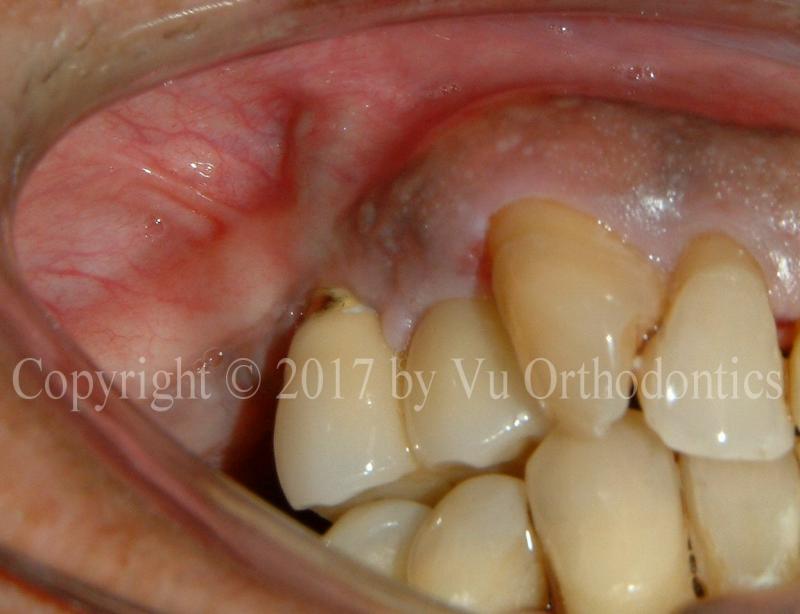
Fig. 3. Implant for Tooth #4 site is outside of the bone and protruding under the soft tissue (photo)
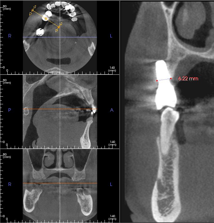
Fig. 4. Implant for Tooth #4 site is outside of the bone (CBCT scan, with buccal-palatal cross-section)
Cement
3M ESPE RelyX Luting Cement is a glass ionomer, resin-modified "luting agent" supplied as powder and liquid, used for permanent cementation of selected indirect restorations and appliances. It is radiopaque, fluoride-releasing, and designed for easy handling and cleanup.
Notes: in dentistry, “luting cement” is redundant because “luting” already means the cementing or attaching process, and a luting agent is the cement used to join a restoration to a tooth. A cleaner phrase is “luting agent” or simply “dental cement."
General information
RelyX Luting cement is intended to bond restorations to tooth structure without a separate tooth conditioner in many cases. It is commonly described as a fast-setting, strong, and easy-to-use permanent cement.
Indications
Reported indications include:
. Porcelain-fused-to-metal crowns and bridges.
. Metal crowns, bridges, inlays, and onlays.
. Strengthened zirconia, alumina core ceramic restoration
. Prefabricated or cast posts.
. Orthodontic appliances or bands.
Preparation
Typical preparation steps include removing the provisional restoration and all temporary cement, then cleaning the tooth with oil-free pumice paste. The tooth should be rinsed and lightly dried, but not overdried, because excessive drying may increase postoperative sensitivity.
Directions for use
The product is mixed from powder and liquid, commonly in a 1:1 scoop-to-drop ratio, then hand-mixed for about 30 seconds. After mixing, apply a thin layer to the inside surface of the restoration, seat the restoration with firm pressure, and remove excess cement after initial set or after tack light-curing when applicable.
Storage and handling
For syringe-based systems, keep the syringe tip clean, discard the used mixing tip, and replace the original sealing cap; do not store the syringe with a new unused mixing tip attached because it may affect shelf life. General storage should follow the manufacturer’s labeling and IFU conditions for temperature and protection from contamination.
Practical note
Because “RelyX Luting” and “RelyX Luting 2 / Plus” are related but not identical products, the exact mixing ratio, working time, and storage details can vary by version. For clinical documentation or staff training, it is best to match the instructions to the exact package and IFU you are using.
Good Implant Placement
The following are examples showing good implant placements (which were done by the author), using a fully-guided system.
Single Implants
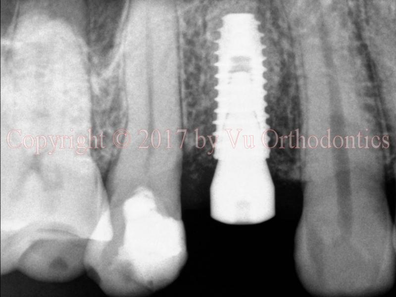
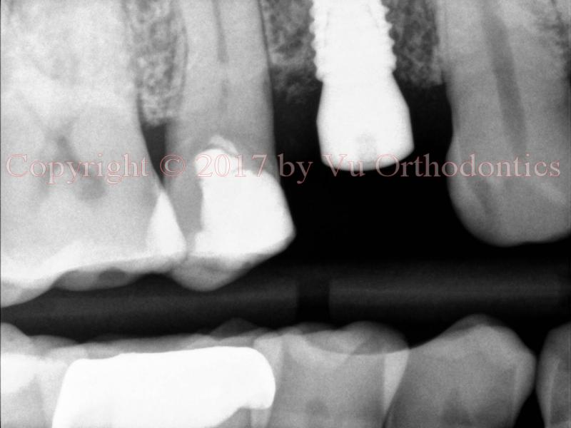
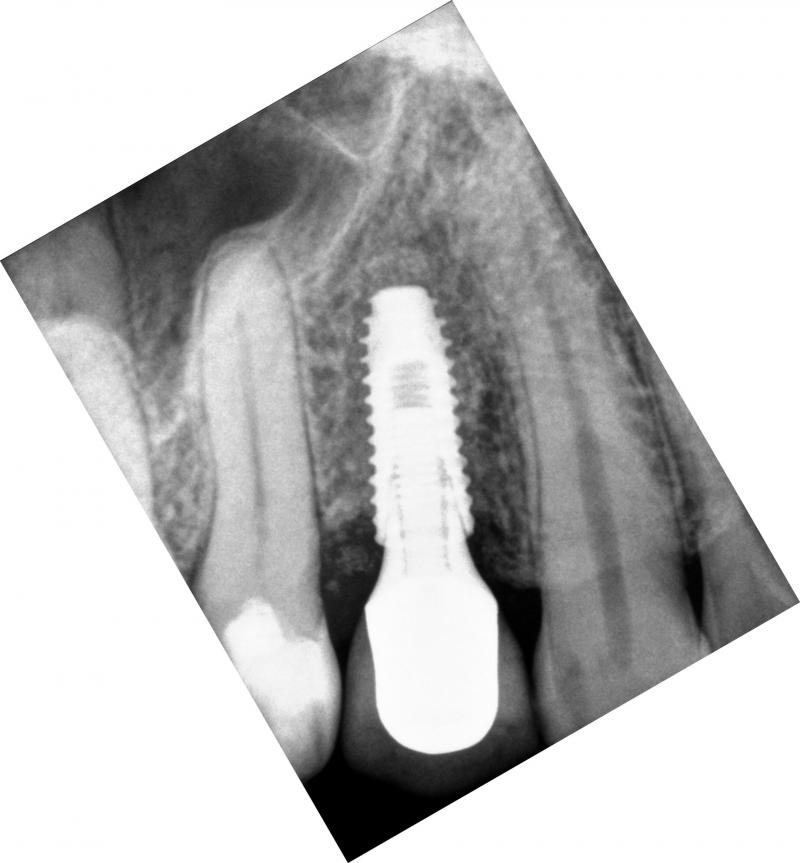
In this case of a single implant, a fully-guided system is used. The implant is perfectly placed center, between the roots of the two natural teeth (Fig. 5). PA means periapival; BW means bitewing. The implant is placed such that its platform is about 0.5-1 mm apical from the alveolar crest.
(a)
(b)
(c)
Fig. 5. A good implant placement: (a) implant and healing abutment (PA view), (b) implant and healing abutment (BW view), and (c) implant, implant abutment, and implant crown (PA view, a month later)
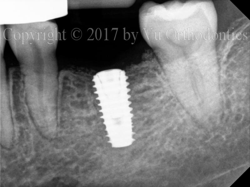
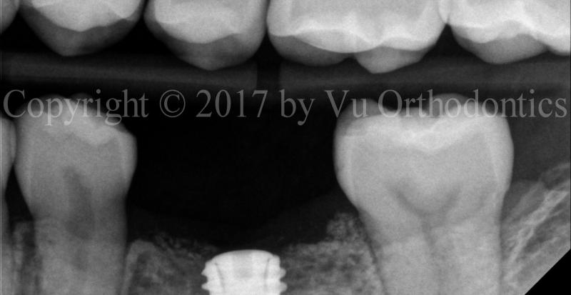
Another example shows a good implant placement (which was done by the author, Fig. 6), using a fully-guided system.
(a)
(b)
Fig. 6. A good implant placement, showing implant and cover screw: (a) PA view, (b) BW view
Multiple Implants
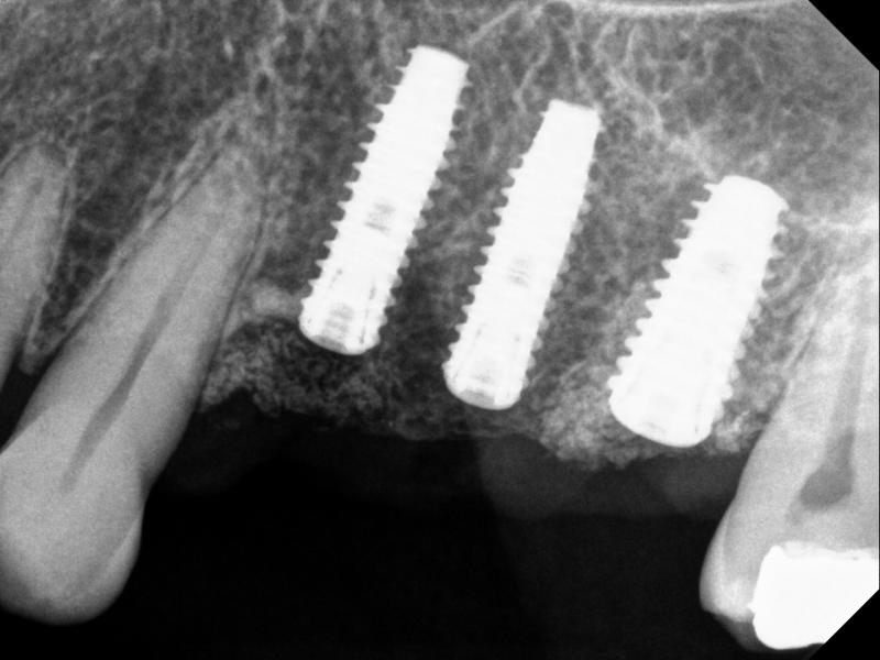
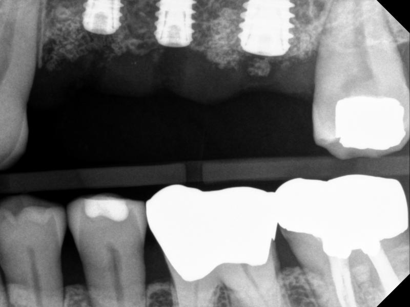
The following is an example of a multi-implant case, in which there is no room for error. Thus, a fully-guided system must be used for implant placement (Figs.7 & 8)
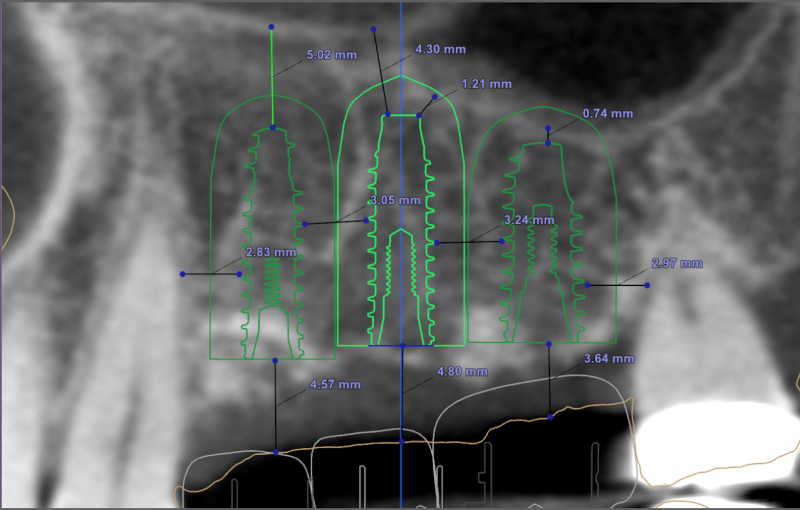
Fig. 7. A multi-implant case, fully guided (Sites #12, #13, and #14): planning
(a)
(b)
Fig. 8. A multi-implant case, using fully guided sytem, Sites #12, #13, and #14 -- implants and cover screws: (a) PA, and (b) BW
Note that for Site #14, the implant was tilted a bit to the mesial side (compared to the planning).
A Case that needs Free Gingival Graft (FGG)
For many patients, the posterior of the lower arch needs Free Gingival Graft (FGG) because of poor quality of keratinized mucosa. The case, infra, shows as an example.
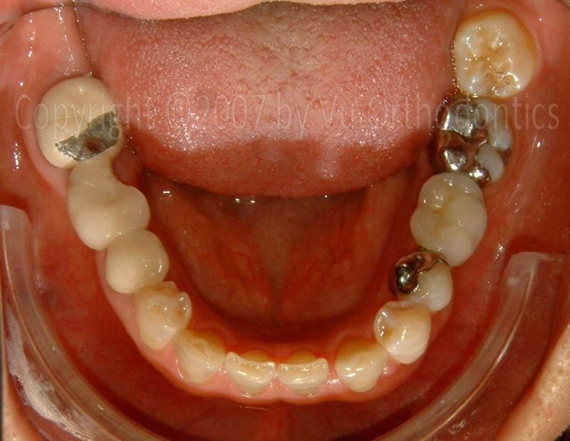
Fig. 9. A broken 3-unit bridge (for the missing Tooth #30)
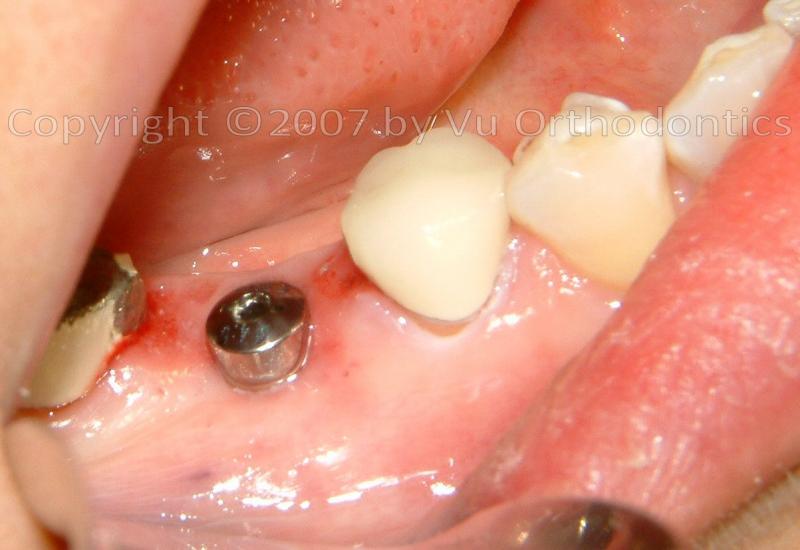
Fig. 10. Poor keratinized mucosa on the buccal side of the implant (with healing abutment)
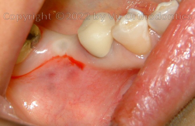
Fig. 11. After the implant was buried (w/ a cap screw), ready for Free Gingival Graft (FGG), poor keratinized mucosa was apparent
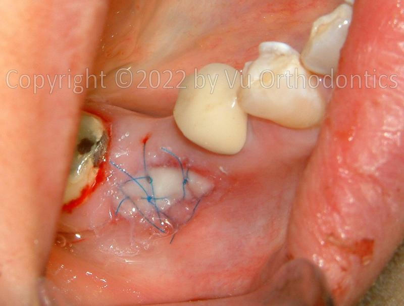
Fig. 12. FGG was performed
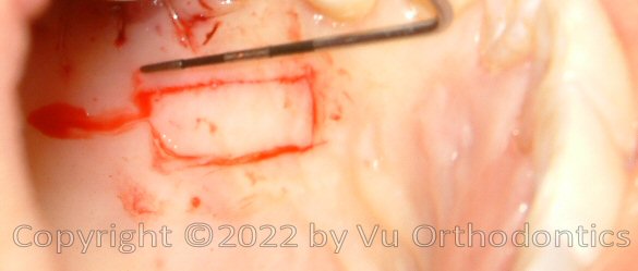
Fig. 13. The donor site on the palate, for the FGG
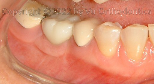
Fig. 14. At the end, good keratinized mucosa is apparent (good seal/protection for the implant, after FGG)
16027 Brookhurst St., Ste. K
Fountain Valley, CA 92708
ph: 714-775-0100
fax: 714-463-2205
drhungvu